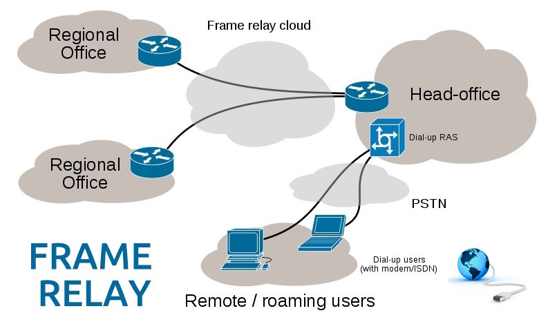
Frame Relay is a WAN protocol that operates at the physical layer and data link layer of the OSI reference model. The main purpose of designing the Frame Relay was to use this technology across Integrated Services Digital Network (ISDN) interfaces. However, with time, its uses also came over to other network interfaces as well.
Frame Relay Devices:
Devices which are a part of the Frame Relay WAN can be categorized under two categories:
- Data terminal equipment (DTE)
- Data circuit-terminating equipment (DCE)
Data terminal equipment (DTE):
As the name suggests, DTE is located at the places in a network where typically data terminates. Thus, DTEs can be considered as the terminating devices for a network because they are located at the end user’s side.
Examples of DTE devices are terminals, personal computers, routers, and bridges.
Data circuit-terminating equipment (DCE):
DCE devices are mostly owned by the service data carrier networks. The DCE equipment is responsible for providing clocking and switching services in a network. DCE is a device which transfers data in the network.
Frame Relay Virtual Circuit:
Frame Relay service provides end to end communication using connection-oriented communication. When connection-oriented communication comes into the play, a predefined communication happens in between each pair of devices.
Each pair of these connections is associated with a connection identifier. A connection identifier is nothing but a number assigned to the communication pair link.
A Frame Relay virtual circuit is nothing but a logical connection created between two DTEs across the internet. Frame Relay offers a bidirectional communication between two DTE devices with a unique identifier called data-link connection identifier (DLCI).
DLCI gives the capability to multiplex a number of virtual circuits across a physical connection.
Types of virtual circuit:
There are two kinds of virtual circuit and those are explained below:
Switched Virtual Circuits
Switched virtual circuits (SVCs) are a kind of temporary virtual connections. They have four operational states:
- Call setup
- Data transfer
- Idle
- Call termination
Permanent Virtual Circuits
Permanent virtual circuits (PVCs) are just opposite to SVCs. Since PVCs are permanent, communication across a PVC does not require the call setup and termination states that are used with SVCs. PVCs always operate in one of the following two operational states:
For those obvious reasons, it has only two operational states:
- Data transfer and,
- Idle